Aem Wiring Diagram
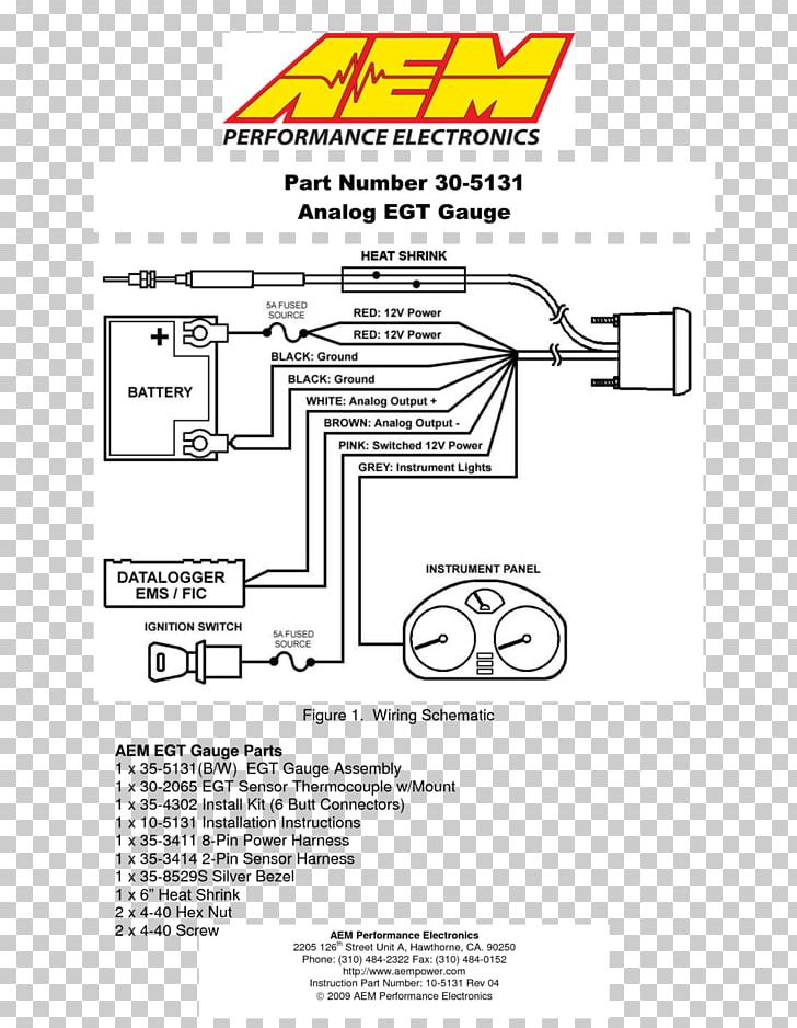
1 trick that we use is to print exactly the same wiring plan off twice. Aem performance electronics aem performance electronics, 2205 126th street unit a, hawthorne, ca 90250 phone:

Aem Water Methanol Kit Wiring Diagram Download
Aem wideband wiring diagram wiring diagram is a simplified up to standard pictorial representation of an electrical circuit it shows the components of the circuit as simplified shapes and the capability and signal associates along with the devices.
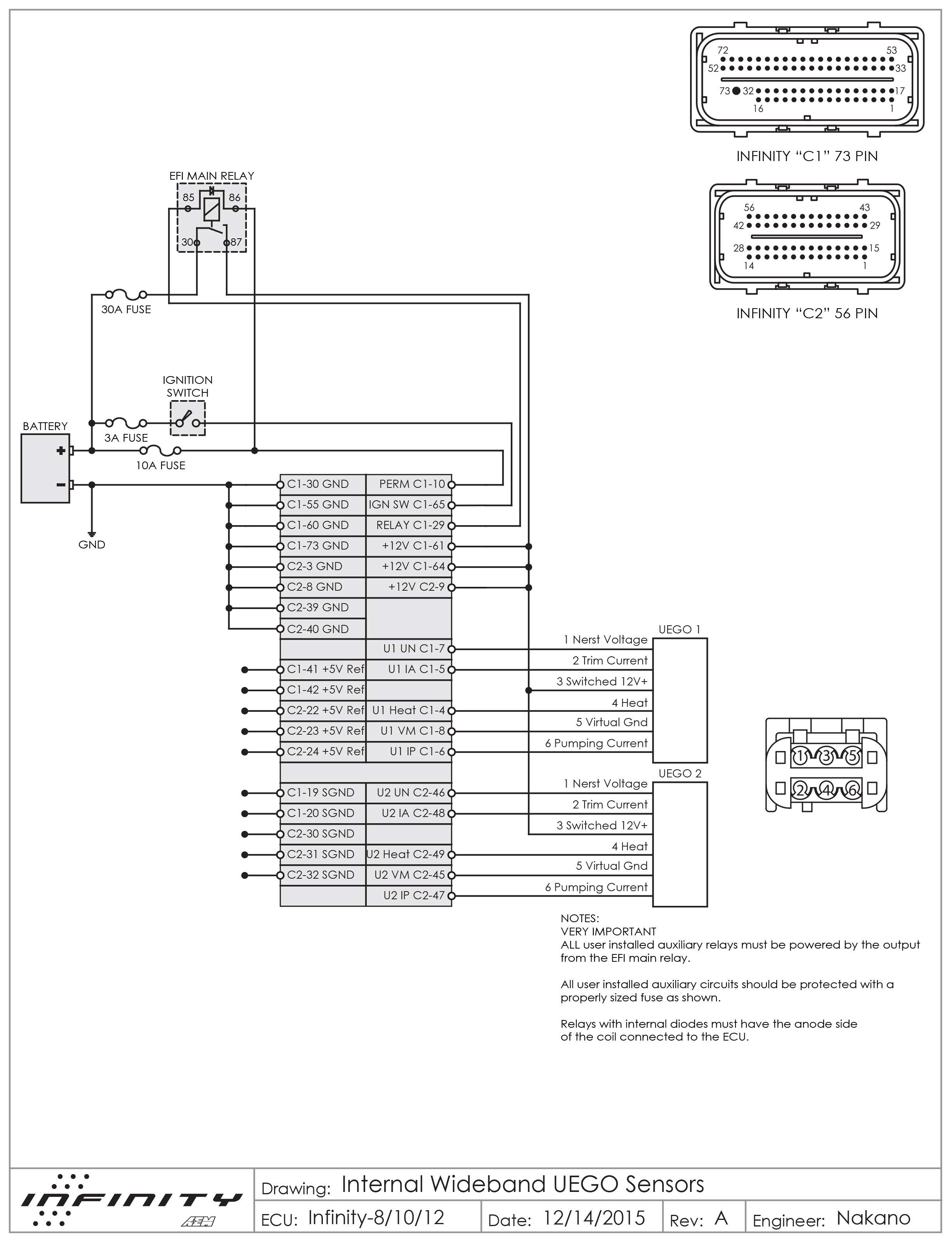
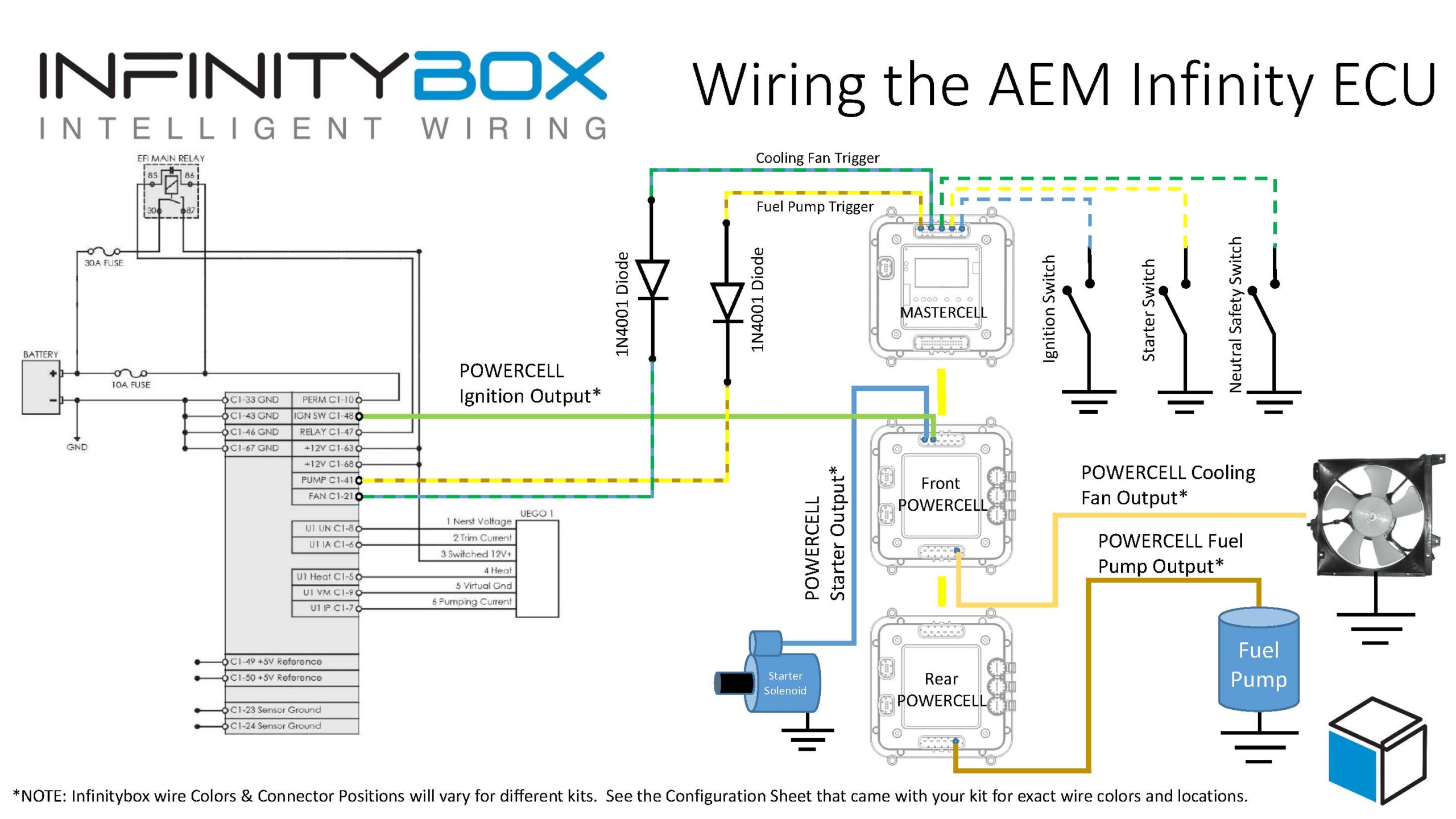
Aem wiring diagram. This makes the process of assembling circuit easier. Aem air fuel gauge wiring diagram wiring diagram is a simplified welcome pictorial representation of an electrical circuitit shows the components of the circuit as simplified shapes and the talent and signal friends surrounded by the devices. This blog post and wiring diagram are only going to cover the connections between your ecu and the infinitybox system.
However, this diagram is a simplified version of this structure. Each output on the for short circuit). Tried in the performance section.
All connectors must be removed without damage to work properly with the aem ecu. Technician familiar with efi sensors, actuators and wiring. See the aem manual for the rest of the wiring details.
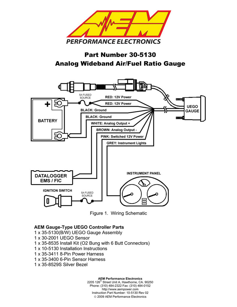
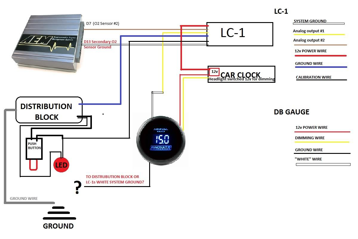
Aem uego gauge air fuel ratio controller installation manual aem cdi coil setup diagram. B) carefully disconnect the wiring harness from the ecu. Please follow this suggested wiring diagram when adding accessories such as uego gauges, map sensors, iat sensors, or switches for use with the ems.
Check out our performance products today! Each part should be placed and connected with different parts in particular way. This diagram provides advice of circuit components in addition to their placements.
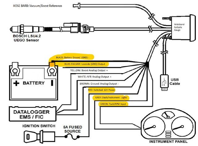
The blue wire from the aem (for aem ems see page 4) serial output (optional) the serial output can be used for data logging when an efi system is not accessible. If you are searching for a supported application for a cd carbon dash or infinity ecu, search using the manufacturer name (for example.
It will also include the details on the fuel pump and the cooling fan. They are designed for installation in the control cabinet (din rail). Avoid excessive stress or pulling on the wires, as this may damage the wiring harness.
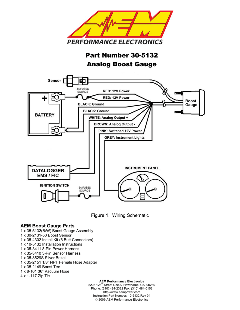
It consists of instructions and diagrams for various varieties of wiring methods and other items like lights, home windows, etc. • direct control of the outputs via ems 4 input module. 1 x (b/w) uego gauge assembly.
Welcome to my blog here i will show you a little more what you are looking for aem 35 wiring diagram below there are.find best value and selection for your aem wideband o2 air fuel uego gauge only 35 tested works great search on ebay. A water methanol mix will increase the charge density of your mixture. 8 channel cdi's have 2 i/o harnesses.
I pulled the wiring harness off the gauge and the pins fell off the connector. 1 pump ground 16 awg orange connect to ground (black) wire of pump. 3 led + 20 awg violet connect to positive (red) wire of external led.
Aem wire making contact with this terminal. Ecu terminations with mini harness, p/n 30. This should be the only aem wire making contact with this terminal.
When you employ your finger or stick to the circuit together with your eyes, it's easy to mistrace the circuit. This should be the only aem wire making contact with this terminal. Aem holds no responsibility for any engine damage that results from the misuse of this product!
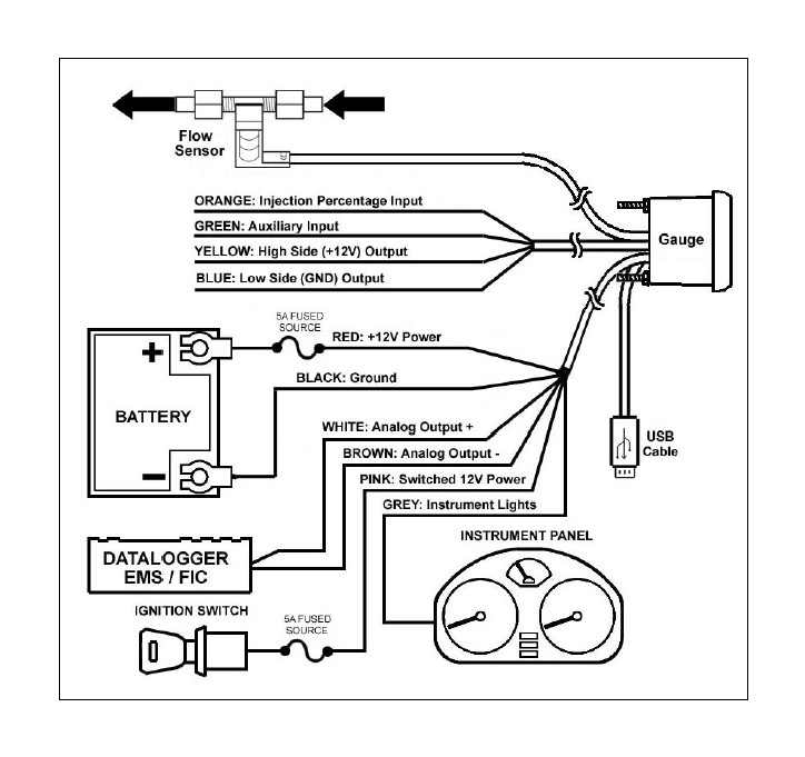
Via sliding switches on the device (see connection diagram). Aem offers a variety of aftermarket wiring harnesses from plug and play applications to programmable options. Note that wire polarity is not important for the air temperature sensor.
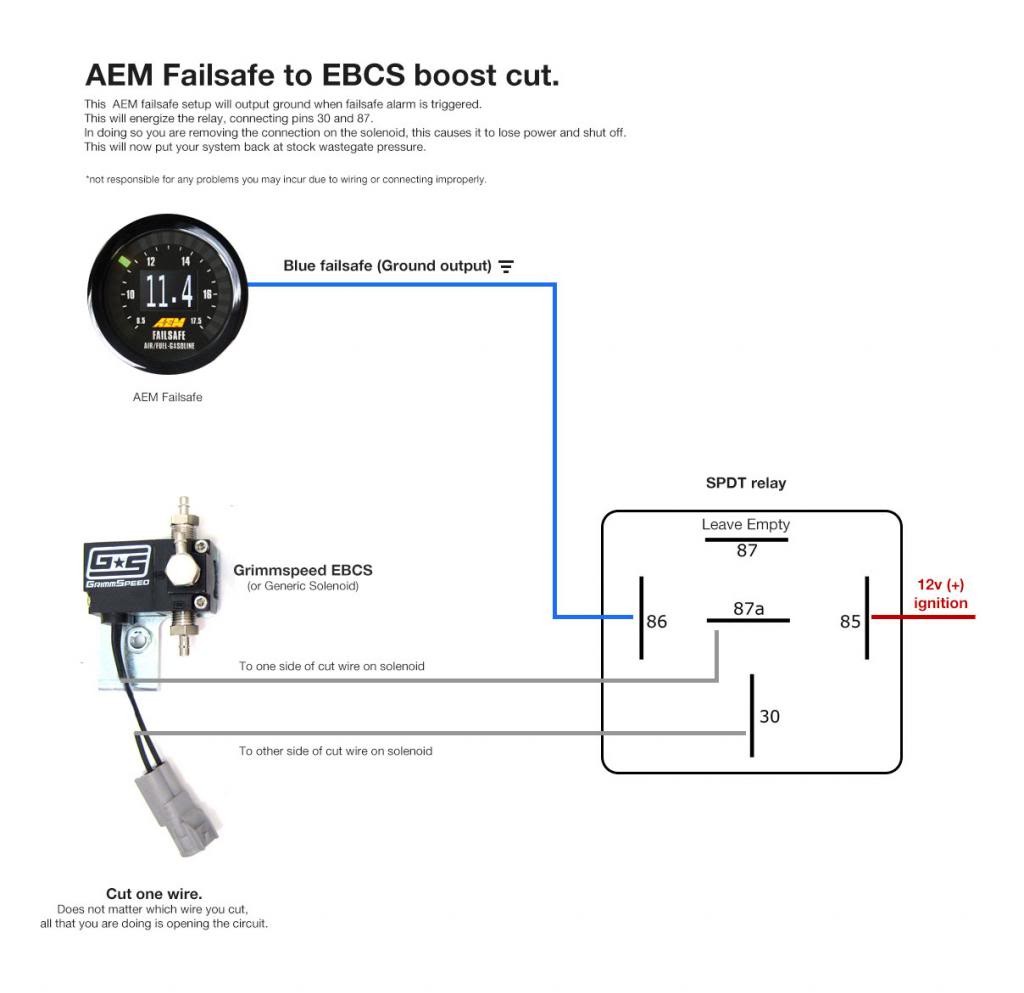
If not, the structure will not function as it ought to be. Do not cut any of the wires in. 10.12.2018 10.12.2018 4 comments on aem tru boost wiring the aem tru boost is one of the easiest to install electric boost connect those 2 wires to the boost solenoid where ever you decide to mount.
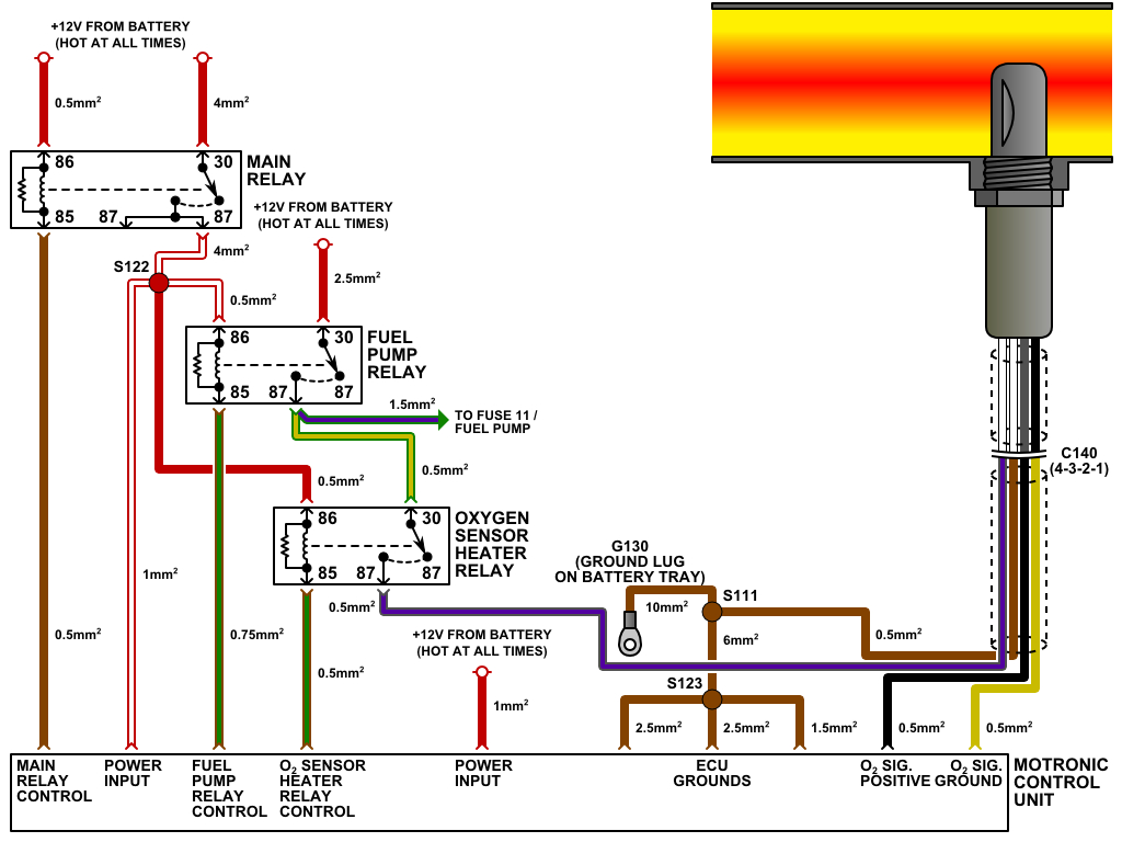
Aem air fuel ratio gauge wiring diagram bosch 5 wire wideband o2 sensor wiring diagram sensor wire harness and connector are sealed the wiring diagram for the wideband sensor typically has six wires the resistive i would guess the 4.1g/2g aem uego wiring | dsmtuners1g/2g aem uego wiring | dsmtuners. Aem x series wideband wiring diagram from lib.americanmuscle.com print the cabling diagram off in addition to use highlighters in order to trace the signal. +5v sensor power switched input 41 sensor ground iat sensor 29 26 aem ems p/n:

Aem Wiring Diagram Wiring Diagram Networks

Aem Wideband Wiring Diagram 16v Car
Aem 35 8460 Wiring Diagram For Your Needs
Aem Air Fuel Gauge Wiring Diagram

How To Install Aem Wideband On Honda Civic Eg/integra & Enable Data Aem Wideband Wiring
Aem 35 8460 Wiring Diagram For Your Needs
Wiring aem uego Forums

Aem Wiring Diagram Wiring Diagram Networks

How To Install Aem Wideband On Honda Civic Eg/integra & Enable Data Aem Wideband Wiring
Aem Wideband Wiring Diagram

Collection Of Aem Water Methanol Kit Wiring Diagram Sample
Aem Air Fuel Gauge Wiring Diagram
Aem Water Injection Wiring Diagram Wiring Diagram
Wiring the AEM Infinity ECU Infinitybox

Aem Wideband Wiring Diagram 16v Car

Aem Wideband 358460 Wiring Diagram For Your Needs

Aem Wideband Wiring Diagram 16v Car
Aem Wideband Wiring Diagram Cadician's Blog
Aem Fic Wiring Diagram 2


